Cisco ACI Fundamentals: ACI Components
Share this page:Before we get deeper into the ACI (Application Centric Infrastructure) as the Cisco’s official SDN solution, we need to clarify a few terms that will be used:
- SDN is a concept that introduces the Networks that are configured and defined using the Software. You can read more about the SDN and Network Virtualization in one of my previous posts.
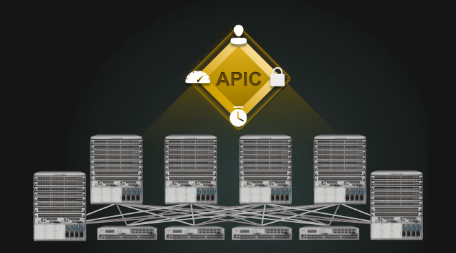
- APIC (Application Policy Infrastructure Controller) is the SDN controller that Cisco ACI architecture uses as the Management Plane.
- Spine and Leaf is also known as the ACI Fabric. This architecture was explained in my VMware NSX introduction here. In the ACI world Spine and Leaf are the Cisco Nexus 9000 Series Switches (N9k) in the ACI mode, and they are the Control and the Data plane of the ACI.
- VXLAN (Virtual eXtensible LAN) is the encapsulation technology on which all the SDN solutions are based, because it permits users on different subnets, even on remote routed networks, to see each other as if they were on the same L2 Segment. Read more about how VXLAN “works” in my previous post here.
- TEP (VTEP) or VET is the Virtual Tunnel End Point. An VTEP is like an SVI on the Switch, because those are the Software defined interfaces. When you deploy the APIC (ACIs SDN Controller), it is used to define the DHCP pool, and when this information is passed on to the Spine Switches - the Spines are used as the DHCP server for all the VTEPs. By default the assigned range of the addresses is 10.0.0.0/16 (this range can be changed). These addresses are INTERNAL to the system.
APIC Controller simply works as the Management of the entire Fabric, and the Fabric itself is doing the entire job, because the Fabric is the Control plane. If you unplug the APIC –your network keeps working exactly the same, because the policies are already deployed, and the fabric itself is handling the control and the data plane.
Dealing with ARP is one of the biggest advantages that the new ACI Fabric provides, and all the other SDN solutions on the market simply ignore this part. Every time there is a change in the VM-s, a Gratuitous ARP (GARP) is sent to the LEAF, and forwarded to SPINE using the COOP protocol. Then the COOP table of the SPINE is being Updated, and propagated to the other SPINEs. You have the option to set the ARP flooding, and it this case the ACI fabric tarts ARP like the traditional Network. There is no interconnection between SPINEs and no interconnection between LEAFs.
How ACI applies the VXLAN: In ACI VXLAN is applied in a different way then, for example, in the VMware NSX, or any other VXLAN-enabled solution, because it has the TrustSEC header “built” into the VXLAN native implementation. It’s applied as the Overlay, exactly like the MPLS Label, with all the PUSH, POP and SWAP operations, where the VTEPs represent the Endpoints where all the VXLAN bytes are added. Why did they use VXLAN and not MPLS Labels? All the Virtual Switches use and understand the VXLAN, and not MPLS. It’s also similar to LISP, but there is a difference in some of the control bits.
IMPORTANT: In cases of FCoE, OTV or the DTI is needed – Nexus 9k does not apply to the customers needs, so we need to use N5k or N7k series and we need to exclude it from the ACI environment. FCoE and OTV are on the ACI Roadmap, so - lets see what happens.
Why do we normally use a Merchant Silicon: Basically it’s used cause it’s built to support the standard based capabilities. The Fabric in the ACI must be a 40G Fabric. There are Cisco custom ASIC specific to the Nexus 9K Switches only:
- ALE – Application Leaf Engine
- ASE – Application Spine Engine
There is another major difference between the “packet forwarding” on Leaf and Spine level:
- Spines: FIB is the Major Forwarding Table, and the Nexus 9336 is the only switch that can assume this role (Jan2015).
- Leafs: CAM is the Major Forwarding Table.
Restful API Calls
Restful API: If you don’t have something you would like to have in the Web GUI of the ACI – you can program it and integrate is using the API. You may pick up the tool you want for this, but my favourite is the POSTMAN, which can be found the Chrome App Store. Using the POSTMAN you can GET (capture) the API commands that are used to do some operation, and modify and repeat it using the POST command. Each GUI action can be captured as the API code and then be modified and executed. APIC supports:
- Northbound APIs (REST API and Python SDK called “Cobra”).
- Southbound APIs (OPFlex and Dev. package).
Every time the GUI contacts the ACI Infrastructure, it uses the REST API. CLI, GUI and SDK all actually use the REST API, and the payloads are XML or JSON. On the diagram below there is an Object Browser called Visor (view, in Italian), but at this moment (Apr2015) it’s only available to Cisco employees.

There is a very Programmable Object Model of ACI and its based on MIT (not the University, the Management Information Tree) and used as a Data Base, where every branch represents a functional area, and every node is a managed object (has a CLASS and a globally unique Distinguished Name formed by a parent name and the relative name, such as - polUniverse is where all the policies are, and the compUni is the Computer Universe).

There are the 3 basic components of ACI:
- ACI Fabric, which are basically the N9k Leaf and Spine Switches.
- APIC, which is the API controller, the cluster that runs the system.
- Logical Model designed in accordance with the concept of ANP – Application Network Profiles (a concept that will be explained later in the post).
All of this is based on Linux, and we can get anywhere within this Architecture using the CLI.
The main idea is that we need to create the Logical Model to support the application. Two hosts should talk if we want them to, and should not talk if we don’t want them to, regardless if they’re on the different Subnet, different IP Network, different VRF (Private Network in the ACI architecture) or the same one.
ECMP (Equal Cost Multi-path Routing) is the routing protocol on the Access Layer that adds the Routing, load balancing and eliminates the STP. The concept is related to Spine-Leaf Architecture (also called Clos architecture).
End Point Group (EPG)
EPG is a group of objects that use the same policy (something like the VMware vSwitch Port Group, and it can be what you want it to be, some of the examples are Security, QoS, or L4-L7 services). This is also a Security Zone, and we use the EPG as the Policy Instatiation point. We actually group the End Points (Servers for example, or any other Grouping characteristics) that need to have the same security policy applied. AEP (Attachable Entity Profile) links the Physical Interfaces to the EPGs. AEP provisions a VLAN pool on a Leaf Switch, and the EPGs enable VLANs on the port.
Domains, VMM or Physical, are tied to pools of VLANs, and then to Attachable Entity Profiles (AEPs). By combining a pool of VLANs with a Domain, you are fundamentally defining which VLANs are allowed to be used by the Fabric for each Domain. The AEP is the final piece, and for now we will simply say that it is the glue that takes all of theses “back end” Fabric configurations and attaches them to an interface.
Like in the traditional L2 Network the VLAN is isolated from everything else, and it represents a Security Group. By that analogy, the EPG represents the Security Group within the ACI.
TIP: It is really important to understand that the VLANs in the ACI architecture have only the local significance on the LEAF. One EPG can use the same logical VLAN, but it can be mapped to 2 different VLANs on two different LEAFs.
TIP: vCenter (or any other Hypervisor) communicates with the APIC via the API-s, and that is how the APIC has all the Virtual Machines information, such as their Virtual Ports (Port Groups on vSwitch).
TIP: Any time you create an EPG, you HAVE to associate it to a BD, and vice versa.
Extension of the EPG is done manually. We need to assign the VLAN to an interface, and map it to the EPG. Within the APIC you would need to statically assign the EPG to the interface. This is used when you have the VMs that are directly connected to the Leaf, and you don´t really have a way to place them into a certain EPG. You basically define the Interface they are attached to as the EPG you want to place them in.
Extension of the BD is a bit more complicated, because we need to create a VLAN for each Subnet that the Bridge Domain contains. That is solved by creating a Bridge Outside for each Subnet, which will then be sent within a Trunk port towards the next switch down the path (Client switch connected to the Leaf).
The APIC Policy can be applied to an End Point via the following 3 steps:
- End Point attaches to fabric.
- APIC detects End Point and derives a source EPG.
- APIC pushes the required policy to Leaf switch.
ACI Contract
ACI Contract is a policy between the EPGs, and it basically defines the relations/actions between EPGs. These Contracts are the Policies that are sent to APIC, which then distributes it into the Data Path, or the Fabric.
Tenants
Tenant is a Logical separator for Customer or a Group. Pre-Configured Tenants are:
- Common – Policies that can be accessed by all tenants.
- Infra – Vain overlay infrastructure configuration (Private L3, Bridge Domain).
- Mgmt – Inband and OOB configuration of fabric nodes.
Private Network (Context)
Private Network is basically a VRF. This is what used to be called a Context before the official ACI Launch, June of 2014. So a Private Network is a Child of a Tenant, and the default policy is Enforce (meaning that if there are 2 TEP-s in the same Network, they cannot talk to each other).

The built in multi-tenant support in ACI means that a separate Tenant may be a better solution than simply using a VRF, but it depends on your needs. Less intuitively – the Private Network is where timer configuration for routing protocols are configured – this is important for the configuration of routed connections within the VRF to routers outside of the fabric (L3 Outs).
Private Network can contain multiple Bridge-Domains for separation of layer-2 domains within a VRF.
Bridge Domain (BD)
One of the hardest concepts to explain to the Network engineers, because it reminds to a concept of VLAN, but it can contain various VLANs (Subnets). In ACI VLANs don´t exist inside the Network, only on the Ports. Bridge Domain is basically a Subnet Container. When you define the unicast IP address/L3 Network and it´s automatically in the routing table. The MAC address must be unique inside the Bridge Domain the same way as the IP address needs to be unique within the VRF. A BD belongs to ONLY ONE Tenant, but a Tenant can, of course, have various BDs. A BD may have more than one subnet.
In the following Screenshot you can see the parameters you need to define when defining a new BD. Private Network is hierarchically above the Bridge Domain, so you should associate your BD with Private Network, as it ties the L2 domain to the parent L3 domain essentially.

L2 Unknown Unicast is either flooded within the BD or sent to Spine Proxy (default), while the Unknown Multicast is set to flood.
The logical model of all the elements is shown below. A TENANT has “child” Private Networks, and each Private Network can have one or more “child” Bridge Domains, each related to one or more EPG-s.

IMPORTANT: One of the star features of the ACI is the Proxy Database or Endpoint Repository, which helps you see all the details about any IP/MAC that is on the network. You can see when it was connected, where exactly, and where it´s been before. It´s a big Historical Database that helps you see, for example, what happened to any machine in each point of time.